NN Accelerator Setup
Essential steps and guides for configuring the Eagle-N evaluation board and target device for BOS AI SDK deployment. Includes board setup, image flashing, and hardware verification procedures for different installation methods.
How to Setup Eval. Board
How to Set up Environment
Eagle-N A0 Eval. Board Overview

Power requirements
- Input voltage: 100 ~ 240 V - 6.0 A
- Frequency: 50/60 Hz
- Output voltage: 12 V, 20 A
Booting modes
- From PCIE
- From SD/MMC
- From QSPI
Eagle-N A0 Eval. Board Setup Environment to run AI models
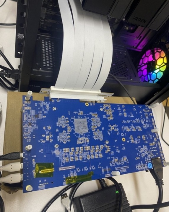
Due to the form factor, the Eagle-N A0 Eval. board may not be directly inserted into PCIe Slot on the motherboard of host PC. A PCIe riser cable in the Eagle-N A0 eval. The board package should be used to connect Eagle-N A0 board and host PC as shown in Figure 1.
Host PC and Eagle-N A0 System Requirements
| Host PC Requirements | |
|---|---|
| CPU | x86 over 8 CPU cores |
| Memory | Over 32GByte |
| PCIE version | Over Gen4 |
| OS version | Ubuntu 22.04 |
Host PC BIOS Setting
Since the N1 board uses the clock provided by the host, the boot sequence between the host PC and the N1 board must be synchronized. Therefore, the N1 board is designed to wake the host PC through a wakeup signal from the PCIe endpoint. As a result, the BIOS settings on the host PC need to be modified according to the values shown in the two tables below. Note that at present, the GIGABYTE BIOS is the only configuration that has been officially validated for use as a host PC. Although other BIOS types may operate correctly when configured in a similar manner, their compatibility with the current N1 software version has not been verified yet.
| Item | Setting value |
|---|---|
| Wake on PCIe / Wake from PCIe | Enable |
| PME Event Wake Up | Enable |
| S5 Wake on PME | Enable |
lspci -v shows the evaluation board information when the board and Host PC are successfully connected.
- The default BAR size of Eagle-N A0 evaluation board is 128MB
$ lspci -v
01:00.0 Co-processor: Synopsys, Inc. DWC_usb3 / PCIe bridge
    Flags: bus master, fast devsel, latency 0, IRQ 156
    Memory at a8000000 (32-bit, prefetchable) [size=128M]
    Memory at a0000000 (32-bit, prefetchable) [size=128M]
    Memory at b0000000 (32-bit, prefetchable) [size=2M]
    Capabilities: <access denied>
    Kernel driver in use: bos
    Kernel modules: bos
How to Boot the Eval. board
There are four steps to get the N1 eval. board started with host PC.
- Connect a host PC and N1 Eval Board using PCIe cable and Connect USB-to-type C cables to see console logs. There are two type C and one microUSB (a.k.a type B) ports on the board as figure 1.
Each of the cables supports two ports, so there will be 4 serial ports as shown below once you connect the cables to host PC and Eagle-N A0 board. The console terminal can be opened to each of the serial parts shown below.$ ll /dev/ttyUSB*
crw-rw---- 1 root dialout 188, 0 Nov 3 17:42 /dev/ttyUSB0
crw-rw---- 1 root dialout 188, 1 Nov 3 17:42 /dev/ttyUSB1
crw-rw---- 1 root dialout 188, 2 Nov 3 17:42 /dev/ttyUSB2
crw-rw---- 1 root dialout 188, 3 Nov 3 17:42 /dev/ttyUSB3
- Eagle-N A0 eval. board booting.
Initially, booting images are fused on NOR flash and eMMC (as default) on the eval. board when the board is shipped. So once the board is powered on, the booting process proceeds automatically and once it is done, the system will boot directly into the Linux kernel. The serial port,/dev/ttyUSB0, below could vary. To log into the Linux Kernel, use below account and password:- username:
root - password:
bossemi.
Poky (Yocto Project Reference Distro) 4.0.21 n1bos /dev/ttyS0

n1bos login: root
password:

root@n1bos:~# - username:
- If any key is hit during the Uboot and return to the Uboot prompt, to boot from Uboot to Linux kernel, use below command:
Hit any key to stop autoboot:   0
u-boot =>
u-boot => run bootcmd_bootwithmode
Checking PCIe link connection status
Run lspci -v command from the terminal in the host PC, then “Synopsis, Inc. DWC_usb3..” should be found from the output results shown below.
-
In the case of a 128MB BAR size
$ lspci -v
01:00.0 Co-processor: Synopsys, Inc. DWC_usb3 / PCIe bridge
    Flags: bus master, fast devsel, latency 0, IRQ 156
    Memory at a8000000 (32-bit, prefetchable) [size=128M]
    Memory at a0000000 (32-bit, prefetchable) [size=128M]
    Memory at b0000000 (32-bit, prefetchable) [size=2M]
    Capabilities: <access denied>
    Kernel driver in use: bos
Kernel modules: bos -
In the case of a 512MB BAR size
$ lspci -v
01:00.0 Co-processor: Synopsys, Inc. DWC_usb3 / PCIe bridge
    Flags: bus master, fast devsel, latency 0, IRQ 156
    Memory at 60000000 (64-bit, prefetchable) [size=512M]
    Memory at 48000000 (64-bit, non-prefetchable) [size=128M]
    Memory at 50000000 (32-bit, non-prefetchable) [size=2M]
    Capabilities: <access denied>
    Kernel driver in use: bos
    Kernel modules: bos
How to Fuse New Images
Step-by-step guide for updating the Eagle-N evaluation board with new bootloader and kernel images using USB fastboot. Covers fastboot setup, driver installation, image preparation, and board flashing procedures for system updates.
In the case that the board needs to boot up with new booting images, the current booting images on flash areas should be replaced with new booting images. USB fastboot is used for booting image update which is a tool within the android framework. To use the USB fastboot, a corresponding driver, called android driver, should be installed on host PC too.
The steps below show how to install the android driver on host PC and how to download new booting binary images to the boards using USB fastboot.
Step 1: Setting the configuration of fastboot on host PC with Ubuntu
-
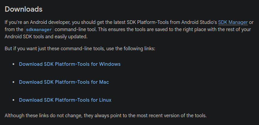
Installing fastboot Download android platform-tools from SDK Platform Tools release page
Unzip the downloaded archive to the proper location.( eg.
/home/bos/android/)$ unzip platform-tools-latest-linux.zip
Archive: platform-tools-latest-linux.zip
inflating: platform-tools/NOTICE.txt
inflating: platform-tools/adb
inflating: platform-tools/etc1tool
inflating: platform-tools/fastboot
inflating: platform-tools/hprof-conv
inflating: platform-tools/lib64/libc++.so
inflating: platform-tools/make_f2fs
inflating: platform-tools/make_f2fs_casefold
inflating: platform-tools/mke2fs
inflating: platform-tools/mke2fs.conf
extracting: platform-tools/source.properties
inflating: platform-tools/sqlite3
$ ls platform-tools
lib64/ fastboot* mke2fs*
NOTICE.txt hprof-conv* mke2fs.conf
adb* make_f2fs* source.properties
etc1tool* make_f2fs_casefold* sqlite3*To make it easier to user, add the directory to the
PATH$ export PATH=$PATH:/home/bos/android/platform-toolsMake sure the version of the installed package is '35.0.2-12147458' or later.
$ fastboot --version
fastboot version 36.0.0-13206524
Installed as /home/bos/android/platform-tools/fastboot
-
Adding device information by executing
fastboot_usb.shso that fastboot can recognize the USB device.Setting necessary permissions for fastboot to use when the Eagle-N A0 board is connected as USB device.
Execute
fastboot_usb.sh. While the script runs, therootprivilege is required to create/etc/udev/rules.d/51-android.rulesfile. The script is covered.$ cat fastboot_usb.sh
#!/bin/bash
mkdir ~/.android
cd ~/.android
echo 0x3816 >> adb_usb.ini
sudo wget -O /etc/udev/rules.d/51-android.rules https://raw.githubusercontent.com/NicolasBernaerts/ubuntu-scripts/master/android/51-android.rules
echo -e "# BOS\nSUBSYSTEM==\"usb\", ATTR{idVendor}==\"3816\", MODE=\"0666\", GROUP=\"plugdev\"" | sudo tee -a /etc/udev/rules.d/51-android.rules
sudo chmod a+r /etc/udev/rules.d/51-android.rules
- Reboot the host PC.
Step 2: Connecting Eagle-N A0 eval. board to host PC
Figure 1 shows how to connect PC with Eagle-N A0 eval. board to download booting images using USB Type B cable for image download and USB Type C for console, respectively.
NOTE: Confirm that the USB cables should support data transmission.( Do NOT use the cables that support only charging )
To download new booting binaries, fastboot packages should be installed on the host PC. The Eagle-N A0 eval. board should be connected to Eagle-N A0 eval. board first and Eagle-N A0 eval. board should be entered into fastboot mode during uboot phase.
Step 3: Booting into USB fastboot mode.
- Doing power on reset by turning on the power switch. Note that N1A0 eval. board should be connected to host PC before turning on the power switch.
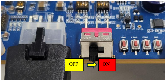
Figure 3. Eagle-N A0 board power switch
- Entering uboot command mode. Once you do power on reset, you can see the console logs as shown below and when you see the message
Hit any key to stop auto boot:, press any key to enter the uboot command mode. Then you can see uboot command shell prompt,u-boot=>.Hit any key to stop autoboot: 0
u-boot=>
u-boot=>
- Configure eMMC/SD card partition by running
mmcpartwritecommand.u-boot=> mmcpartwrite
- Run
fastbootcommand as shown below. If you can seecrq->brequest:0x0(sometimes not shown but that is ok), then Eagle-N A0 is successfully entered into fastboot mode. Now ready to download booting images. (The output message may change or may not be displayed, but if the USB driver is visible on the host PC, it is usable.)Once you runu-boot=>
u-boot=> fastboot 0
fastboot_buf_addr: 0x0000000095000000
fastboot_buf_size: 0x0000000020000000
serial# : EAGLE-N1-A0-FFFFFFFEfastboot 0, the device is ready for receiving booting images from host PC.
- Check if Eagle-N A0 is detected as USB device on the PC using “lsusb” command. If it is detected,
BOS Eagle N1 Bootloader Interfaceshould be displayed as shown below.$ lsusb
Bus 002 Device 001: ID 1d6b:0003 Linux Foundation 3.0 root hub
Bus 001 Device 026: ID 10c4:ea70 Silicon Labs CP2105 Dual UART Bridge
Bus 001 Device 023: ID 214b:7250 Huasheng Electronics USB2.0 HUB
Bus 001 Device 010: ID 3816:1000 BOS Eagle N1 Bootloader Interface
Bus 001 Device 009: ID 26ce:01a2 ASRock LED Controller
Bus 001 Device 001: ID 1d6b:0002 Linux Foundation 2.0 root hub
- Check if
fastboot devicesare correctly detected$ fastboot devices
EAGLE-N1-A0-FFFFFFFE Android Fastboot
- If it doesn't work, check if each of the files,
adb_usb.iniand51-android.rules, is properly created and contains the correct content.$ cat ~/.android/adb_usb.ini
0x3816
$ cat /etc/udev/rules.d/51-android.rules
...
# BOS
SUBSYSTEM=="usb", ATTR{idVendor}=="3816", MODE="0666", GROUP="plugdev"
Step 4: Check the switches of Eagle-N A0
To switch the partition between eMMC and SD card, let choose the corresponding switch as below:
1. SW53
a. 1, 2 LEFT: SD card
b. 1, 2 RIGHT: eMMC
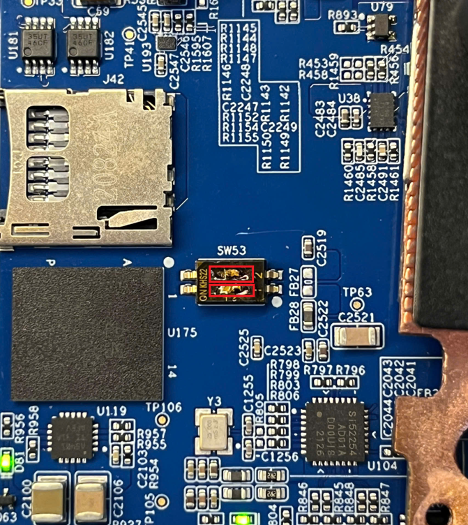
Figure 4. SW 53
2. SW3
a. UP: eMMC
b. DOWN: SD card
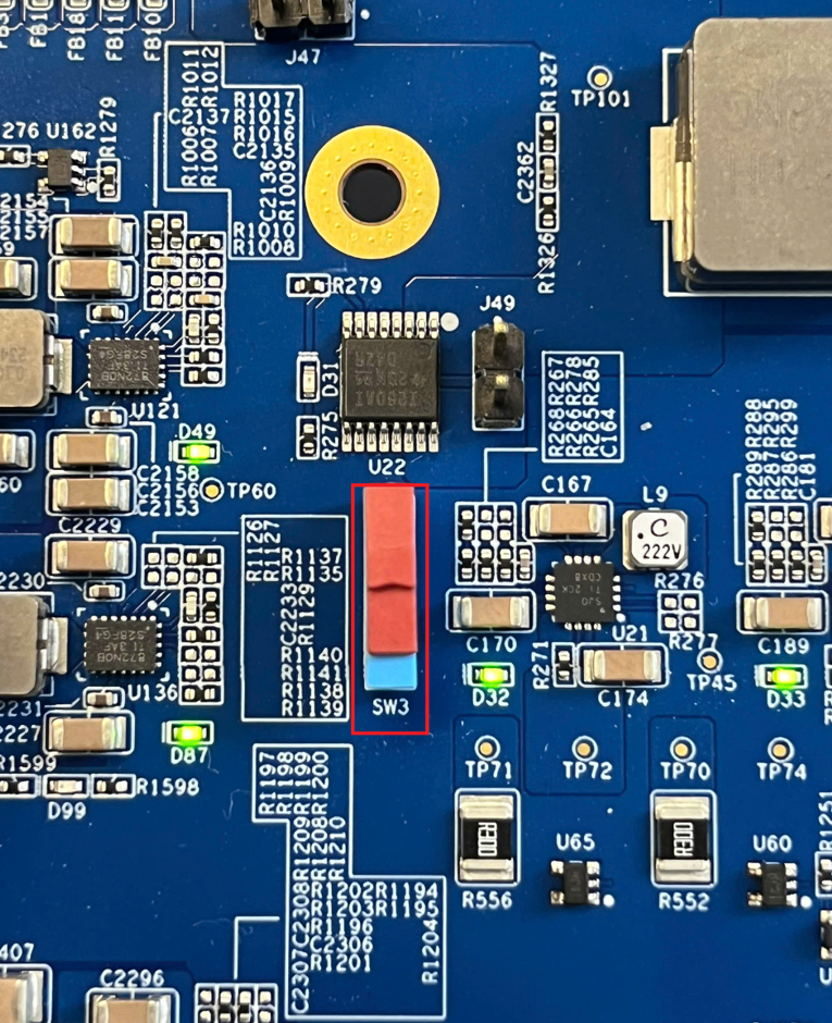
Figure 5. SW3
User can check the selected partition from uboot with mmc info command.
-
in case of using eMMC
u-boot=> mmc info
Device: sdhci@20600000
Manufacturer ID: 13
OEM: 4e
Name: AAM20E
Bus SPeed: 52000000
Mode: MMC High Speed (52MHz)
Rd Block Len: 512
MMC version 5.1
High Capacity: Yes
Capacity: 29.6 GiB
Bus Width: 8-bit
Erase Group Size: 512 KiB
HC WP Group Size: 8 MiB
User Capacity: 29.6 GiB WRREL
Boot Capacity: 31.5 MiB ENH
RPMB Capacity: 4 MiB ENH -
in case of using SD card
u-boot=> mmc info
Device: sdhci@20600000
Manufacturer ID: 1b
OEM: 534d
Name: EC1S5
Bus SPeed: 52000000
Mode: SD High Speed (50MHz)
Rd Block Len: 512
SD version 3.0
High Capacity: Yes
Capacity: 59.7 GiB
Bus Width: 4-bit
Erase Group Size: 512 Bytes
Step 5: Fastboot download commands
After selecting the eMMC/SD card partition, the fastboot flash command is used to download the above images from host PC to the selected partition:
You can check serial number with fastboot devices first, and download images to the eval. board.
$ fastboot devices
EAGLE-N1-A0-FFFFFFFE      Android Fastboot
$ fastboot -s EAGLE-N1-A0-FFFFFFFE flash package n1-bip.bin
Warning: skip copying package image avb footer (package partition size:0, package image size: 1604608)/
Sending 'package' (1567 KB)                    OKAY[   0.115s]
Writing 'package'                              OKAY[   5.842s]
Finished. Total time: 5.958s
If host PC is connected with only one Eagle-N A0 eval. board, you don't need to specify the serial number
$ fastboot flash package n1-bip.bin
Warning: skip copying package image avb footer (package partition size:0, package image size: 1604608)/
Sending 'package' (1567 KB)                    OKAY[   2.735s]
Writing 'package'                              OKAY[   5.745s]
Finished. Total time: 8.484s
After flashing the image, to booting up the system into Linux, reboot the target board and enter the uboot download mode (refer the step 2-2).
When the board is ready, download other images into the eMMC or SD card on the board:
- Kernel device tree blob (DTB)
- Kernel image
- Root file system
$ fastboot flash kerneldtb kernel.dtb
Sending 'kerneldtb' (36 KB)                    OKAY[   0.009s]
Writing 'kerneldtb'                            OKAY[   0.058s]
Finished. Total time: 0.303s

$ fastboot flash kernel kernel.img
Sending 'kernel' (240-9 KB)                    OKAY[   0.935s]
Writing 'kernel'                               OKAY[   2.031s]
Finished. Total time: 2.999s

$ fastboot flash rootfs rootfs_16.ext4
Sending 'rootfs' (16384 KB)                    OKAY[   1.101s]
Writing 'rootfs'                               OKAY[ 196.529s]
Finished. Total time: 197.665s
While downloading the images, you can see the progress from the board.
For example,
u-boot=> fastboot 0
fastboot_buf_addr: 0x0000000095000000
fastboot_buf_size: 0x0000000020000000
serial# : EAGLE-N1-A0-FFFFFFFE
Starting download of 1604608 bytes
...........
downloading of 1604608 bytes finished
current version :0.0.0.1, package version: 0.0.0.1
active_slot: A

...
...


----- Partition update is complete!  ---
BIP version is identical, skipping update
Boot meta is identical, skipping update
New image flag set successfully
---------------------------------------
-- Package update was complete !  -----
---------------------------------------
Eagle-N device binaries
The table below shows the list of binaries that need to be fused onto the board. You can download them after requesting access to the git.
| Partition | Partition name | Image | Description |
|---|---|---|---|
| Package | package | n1-bip-v0.1.0.3_patch1119.bin | Total of image |
| Kernel DTB | kerneldtb | kernel-v0.1.0.3_patch1119.dtb | The DTB of the Kernel |
| Kernel Images | kernel | kernel-v0.1.0.3_patch1119.img | Linux Kernel Image |
| Root File System | rootfs | rootfs-v0.1.0.3_patch1119.img | Linux Root File System. sparse image of 512MB RootFS |